No more jumper plugs - The VL60 gets an upgrade
A brief review
Logic modules offer the possibility of linking signals reliably and cost-effectively. Instead of connecting the sensors in series or parallel, the signals are linked via logic gates from semiconductor technology.
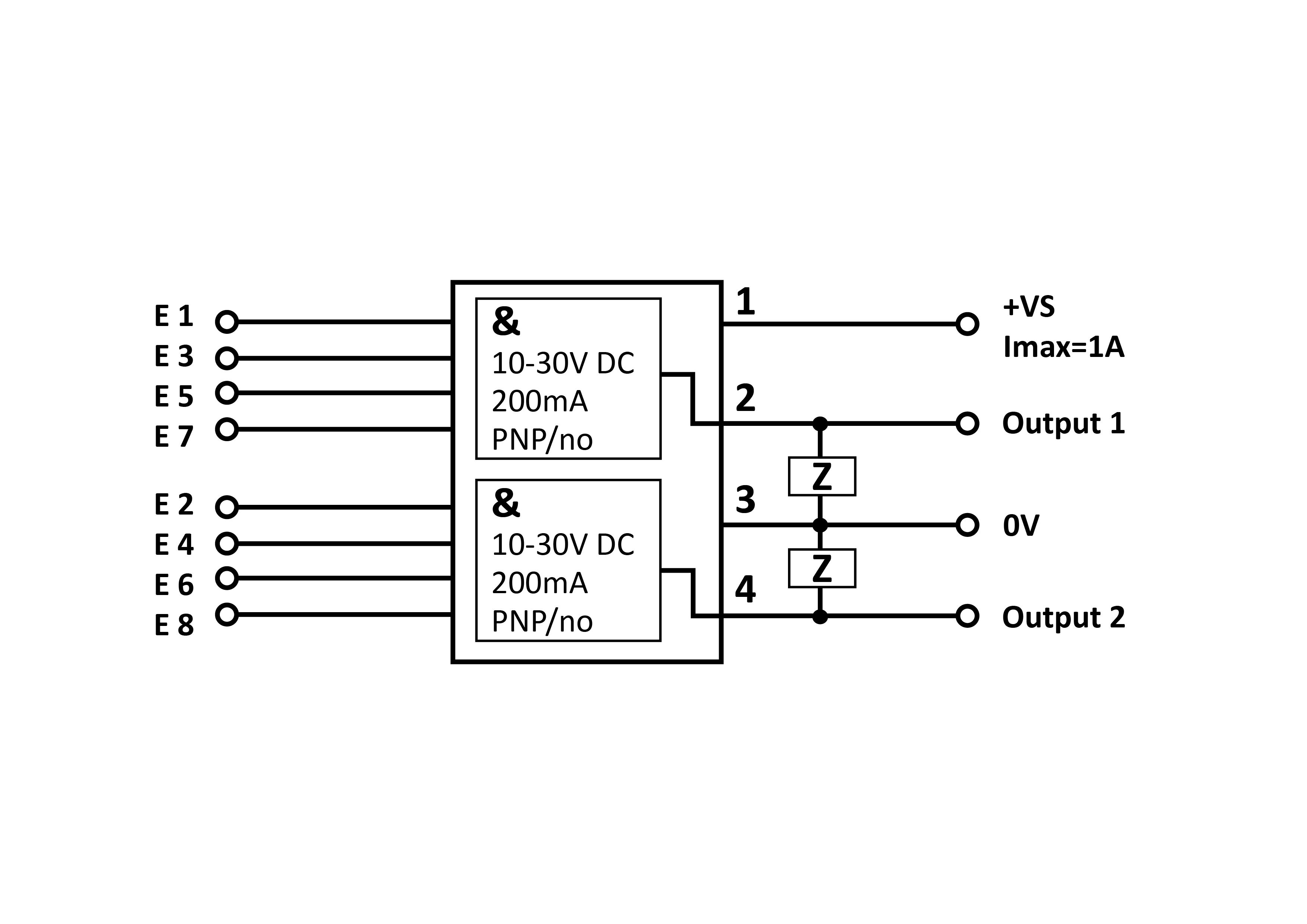
The products in the VL60 series from ipf electronic are logic distributors that are connected via a classic, four-pin M12 plug connection, both on the machine and sensor side. The following illustration shows the circuit diagram of the VL600118 logic module developed by ipf electronic: The voltage supply is looped to the sensor connections. Four logic operations switch the first output and four others switch the second output. This is simple and effective. If not all inputs are assigned, the compound-filled and therefore impermeable simulation connector VK000035 can simply be used to protect them.
The problem with series connection and advantages over parallel connection
ipf electronic's support team has repeatedly received queries from customers because the series connection, in which the switching output of the first sensor supplies the second device with voltage, does not work. Two characteristics are crucial for such a series connection to work: the inrush current of the second sensor and the voltage drop of the first sensor. It often happens that the first sensor in the series switches to short-circuit protection because the inrush current of the second device is too high. This is usually the most common reason why a series connection does not work. Another possibility for wired logic is a parallel connection. This is technically feasible without any problems. With a logic module, however, material and labor costs are saved in the end.
How the VL60 became the VL61
The engineers at ipf have long wanted to make the logic modules more flexible. However, this would involve considerable additional work. With the help of IO-Link technology, a standard solution was developed instead, which can be used to work across systems without a great deal of effort. The new features of the solution are summarized below.
Freely configurable
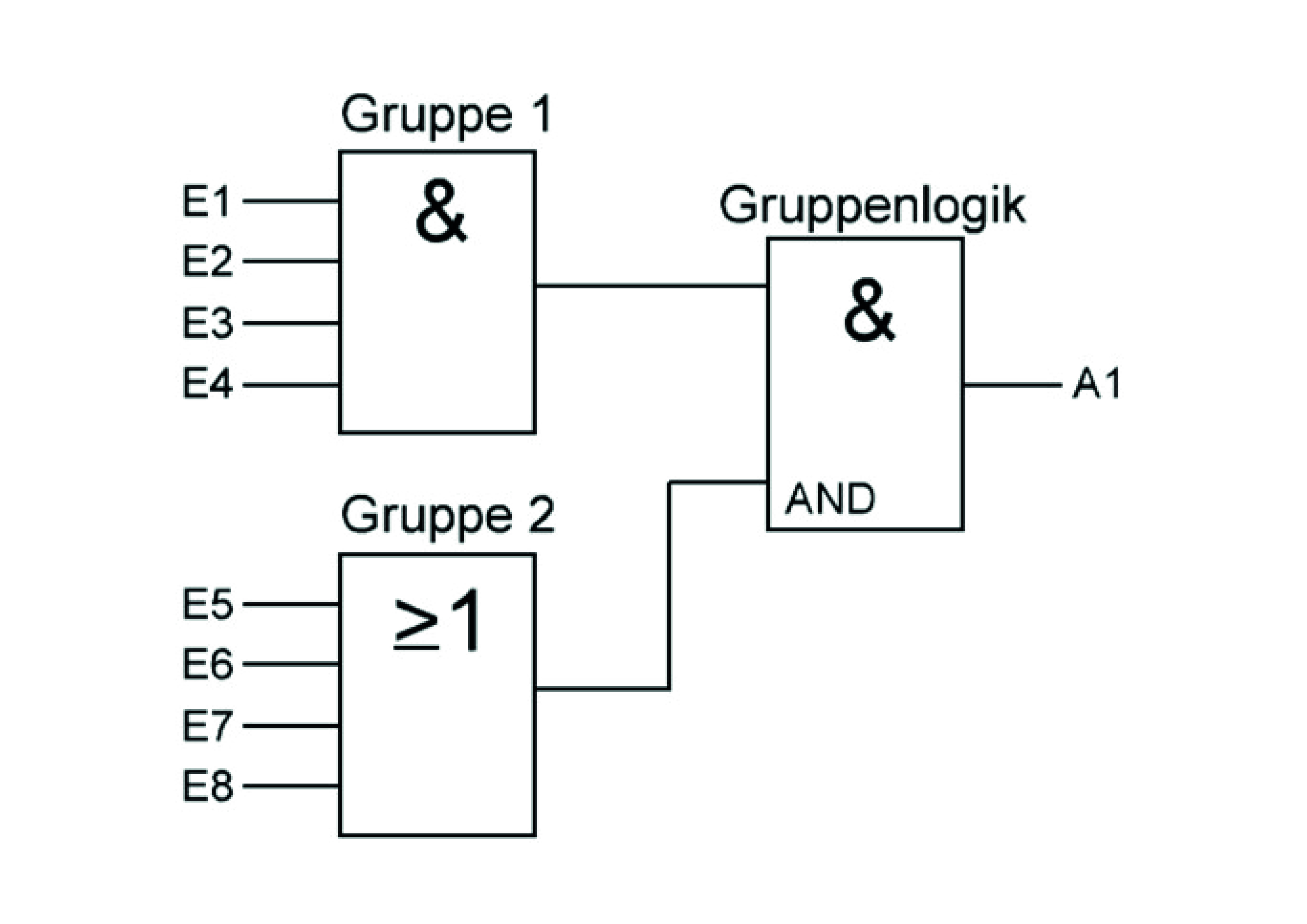
The versions have four or eight inputs that can be freely linked directly to the output. A new option is to be able to combine inputs into two groups per output, which in turn are merged into a group logic that is also freely adjustable. The following example illustrates such a grouping:
The parameterization of the logic module
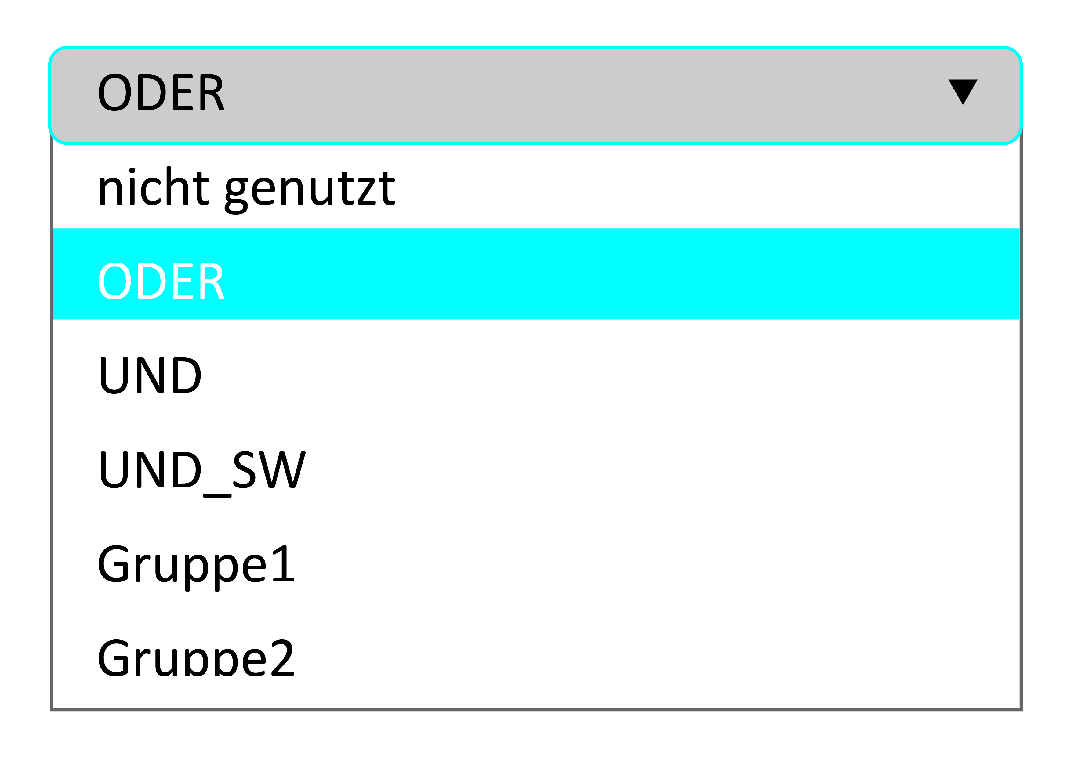
The illustration of a section of the user interface of the IO link master VY000005 shows which options are available for setting the module.
It is also possible to assign the inputs to the two groups described above. Which logic the respective groups follow can be set separately and thus defined.
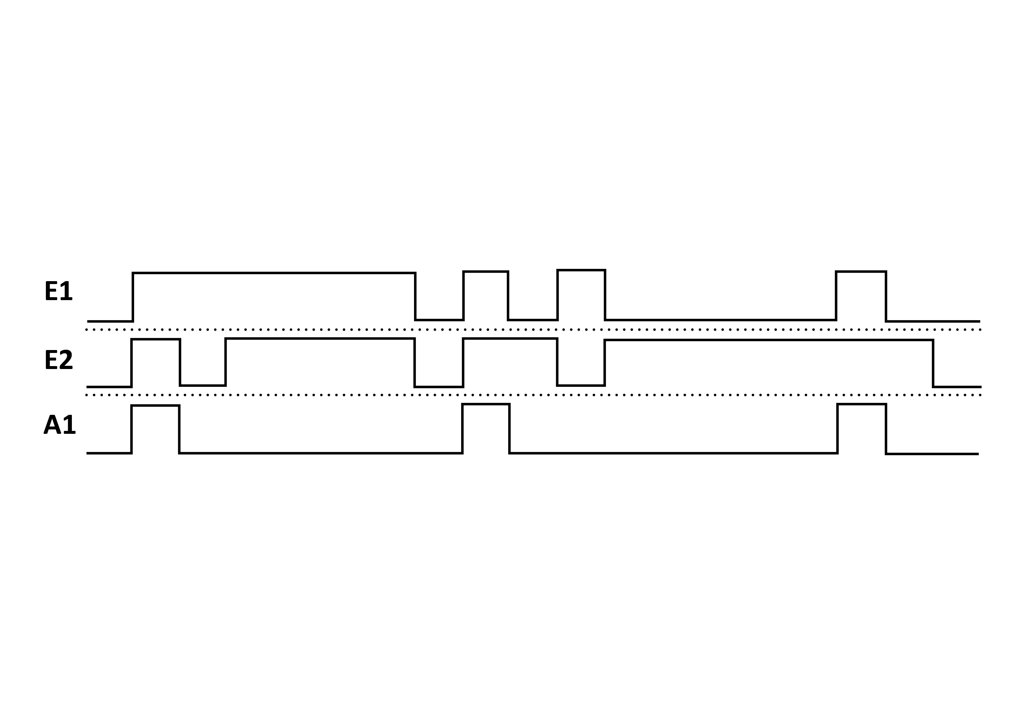
Checking the edge change:
This function ensures that the output only switches when all linked inputs have completed a negative edge change. This indirectly monitors the function of the sensor.